|
The seed for this scope was planted in the Spring of 1995. As my daughter, Michele, struggled to steady the binoculars with a stepladder to look at the full moon she said: "Dad, I sure wish we had a telescope right now!" Knowing nothing about telescopes but wanting to impress her with my engineering skills, I flippantly declared: "It sure would be fun to build one, don't you think?"
After several ATM books and a class of Telescope 101 from the local Astronomy Club President, Bob Wooley (now with Astronomical Adventures), I roughed out a sketch and thus began my (often 2 & 3 times) daily visits to the local Hardware Store for the next 3 months.
|
Several unique Scope construction features are discussed below:
|
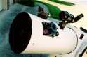 The altitude trunnion box assembly is a "clamshell" design to allow quick'n'easy front/back and rotation positioning of the tube. A piano hinge joins the two halves of the box underneath. A flip of the two trunk latches on top allows the tube to be adjusted for balance and eyepiece positioning comfort as needed. Rubberized cork strips line a portion of the curved profile next to the tube to provide enough frictional gripping of the tube for zenith observations while still allowing easy tube adjustment when unlatched.
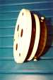
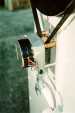
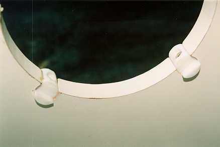
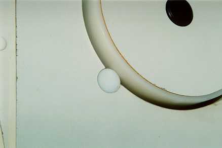
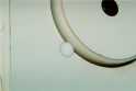 The altitude bearing supports are the typical Teflon® material except that I used 3/4"OD rod stock turned on its side. The altitude bearings themselves are 6"OD flanged Nylon® tube inserts. The small projections on the inside ends of the Teflon® rod ride lightly on the bearing flanges to keep the box offset from the bearing yoke supports.
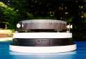
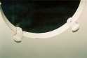
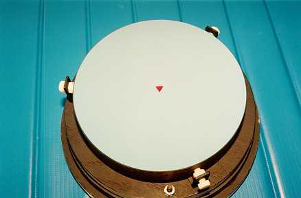
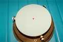 The primary mirror is offset in front of the mirror cell about 3/8" with flattened RTV silicone blobs on top of 3 elevator bolts which allows easy mirror removal for cleaning or recoating and permits a free flow of air underneath the mirror. Lateral mirror movement is restricted by 3 nylon bolts lightly tightened against the mirror's edge.

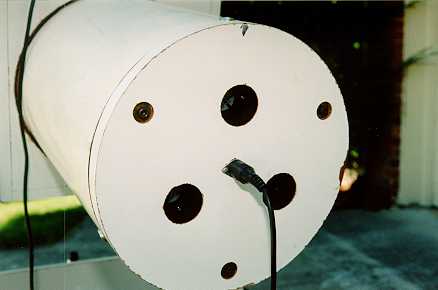
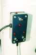 The mirror is cooled by 3 brushless 12vdc "muffin" fans that pull air in at the front end of the tube, down across the mirror face, around the mirror edge and exhaust out the rear. Each fan is controlled separately on the switch box mounted with Velcro® on the right side of the base, and the on/off status of each is indicated with 3 adjacent LED's.
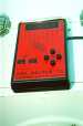
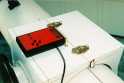
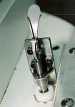
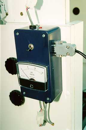
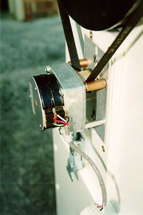
 I installed the Alt/Az drive system in the Spring of 1997 using the "DOB DRIVER II" kit from Tech2000. I augmented the basic kit components with a power supply panel and I spliced Molex® connectors into the motor leads to facilitate easy scope breakdown. The drive control pendant is located on the top of the trunnion box for convenient fingertip access when looking through the finder or eyepiece and attached with Velcro® for easy removal.


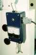
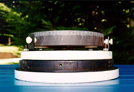
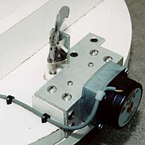
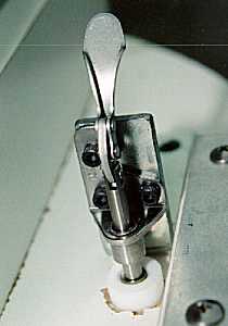
 The Azimuth motor bracket is shimmed to position the knurled edge of the drive wheel 3/32" below the turret base. The wheel drives against the melamine surface of the ground board below. I fashioned a "quick-action" azimuth clutch from a DE-STA-CO "in-line" toggle clamp with a Teflon® foot attached to the action rod. For manual slewing, the clamp lever is pushed down and locked into position lifting the drive wheel off the ground board about 1/16".
| | | | | | |


 The altitude trunnion box assembly is a "clamshell" design to allow quick'n'easy front/back and rotation positioning of the tube. A piano hinge joins the two halves of the box underneath. A flip of the two trunk latches on top allows the tube to be adjusted for balance and eyepiece positioning comfort as needed. Rubberized cork strips line a portion of the curved profile next to the tube to provide enough frictional gripping of the tube for zenith observations while still allowing easy tube adjustment when unlatched.
 The altitude bearing supports are the typical Teflon® material except that I used 3/4"OD rod stock turned on its side. The altitude bearings themselves are 6"OD flanged Nylon® tube inserts. The small projections on the inside ends of the Teflon® rod ride lightly on the bearing flanges to keep the box offset from the bearing yoke supports.
 The primary mirror is offset in front of the mirror cell about 3/8" with flattened RTV silicone blobs on top of 3 elevator bolts which allows easy mirror removal for cleaning or recoating and permits a free flow of air underneath the mirror. Lateral mirror movement is restricted by 3 nylon bolts lightly tightened against the mirror's edge.

 The mirror is cooled by 3 brushless 12vdc "muffin" fans that pull air in at the front end of the tube, down across the mirror face, around the mirror edge and exhaust out the rear. Each fan is controlled separately on the switch box mounted with Velcro® on the right side of the base, and the on/off status of each is indicated with 3 adjacent LED's.

 I installed the Alt/Az drive system in the Spring of 1997 using the "DOB DRIVER II" kit from Tech2000. I augmented the basic kit components with a power supply panel and I spliced Molex® connectors into the motor leads to facilitate easy scope breakdown. The drive control pendant is located on the top of the trunnion box for convenient fingertip access when looking through the finder or eyepiece and attached with Velcro® for easy removal.

 The Azimuth motor bracket is shimmed to position the knurled edge of the drive wheel 3/32" below the turret base. The wheel drives against the melamine surface of the ground board below. I fashioned a "quick-action" azimuth clutch from a DE-STA-CO "in-line" toggle clamp with a Teflon® foot attached to the action rod. For manual slewing, the clamp lever is pushed down and locked into position lifting the drive wheel off the ground board about 1/16".